
Measuring Your Driveshaft
Arizona Driveshaft provides top quality parts and service in an effort to create trust between Arizona Driveshaft and you, the end user. In that on-going effort, we have strived to provide the diagrams on this page for your convenience. Arizona Driveshaft desires to place the correct product in your possession, reassuring the level of trust we work so hard to create. If you still have questions after using these diagrams, please call our skilled personnel to assist you at (480) 898-1957.
- Think – SAFETY FIRST
- Use stable blocking, safety jack stands, and vehicle lifts for safety
- Mistakes are COSTLY!
- Measurements are often as important or more so than the year, make and model of vehicle due to possible changes to the vehicle
- ARIZONA DRIVESHAFT will provide products to client measurements – proper measurement is the responsibility of the end user
- Measurement must be done with wheels and axles under normal vehicle load – Vehicle at level that is high enough to allow proper access for measuring – Proper angle of the pinion
- Measurement for long lengths by tape measure should always pull an inch at the beginning of tape – the end of tape measures can give a false reading due to varying end construction
- Long measurements should be done by two persons and pull tape tight during measurement
- Measure small parts with a straight ruler (preferably metal) and / or a caliper (preferably digital) for greater accuracy
How To Measure Your Driveshaft Length
PDF Diagrams For Download / Print (Click to Download)
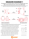
Diagram D1
NEW DRIVESHAFT MEASUREMENT
This diagram is to illustrate how to measure for driveshafts with a slip yoke at the transmission and a u-joint at the differential.
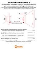
Diagram D2
NEW DRIVESHAFT MEASUREMENT
This diagram is to illustrate how to measure for driveshafts with a slip yoke at the transmission and a flat flange at the differential.
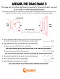
Diagram D3
NEW DRIVESHAFT MEASUREMENT
This diagram is to illustrate how to measure for driveshafts with a u-joint at one end and a flat flange at the other.
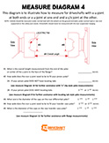
Diagram D4
NEW DRIVESHAFT MEASUREMENT
This diagram is to illustrate how to measure for driveshafts with a u-joint at both ends or a u-joint at one end and a c/v joint at the other.
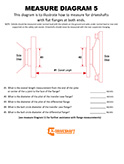
Diagram D5
NEW DRIVESHAFT MEASUREMENT
This diagram is to illustrate how to measure for driveshafts with flat flanges at both ends.
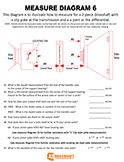
Diagram D6
NEW 2-PIECE DRIVESHAFT MEASUREMENT
This diagram is to illustrate how to measure for a 2-piece driveshaft with a slip yoke at the transmission and a u-joint at the differential.
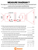
Diagram D7
NEW 2-PIECE DRIVESHAFT MEASUREMENT
This diagram is to illustrate how to measure for a 2-piece driveshaft with u-joints at the transmission and differential.
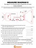
Diagram D8
NEW X FRAME 2-PIECE DRIVESHAFT MEASUREMENT
This diagram is to illustrate how to measure for a X Frame 2-piece driveshaft.
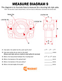
Diagram D9
TAB STYLE YOKE MEASUREMENT
This diagram is to illustrate how to measure for a locating tab style yoke.
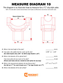
Diagram D10
“C” CLIP YOKE MEASUREMENT
This diagram is to illustrate how to measure for a “C” clip style yoke.
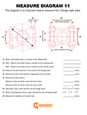
Diagram D11
FLANGE YOKE MEASUREMENT
This diagram is to illustrate how to measure for a flange style yoke